Andrew Arizaga - My Engineering Portfolio

Disclaimer: This project is a work in progress. Updates and improvements are ongoing!

Smart Power Management System
Using Microcontroller

The Smart Power Management System Using Microcontroller is designed to make energy use smarter and easier. It automatically controls lights and appliances based on who’s in the room, adding a personalized touch. Using the ESP32 microcontroller, a custom PCB, and advanced sensors, this project is all about combining practicality with sustainability to optimize energy use without any extra hassle.

Here’s an overview—feel free to look it over!

Project Overview

Project Description

Overview

Smart Power Management Overview

The Smart Power Management System Using Microcontroller is a versatile and energy-efficient solution designed to optimize power usage in modern spaces. It achieves this by automating the control of appliances such as lights, fans, and televisions based on room occupancy and user identification. The system integrates powerful microcontrollers, sensors, and relays, providing a compact and efficient solution for energy management. This innovative approach reduces energy waste while enhancing user convenience and security, making it ideal for smart homes, offices, and other applications.

ESP32-WROOM-32D

ESP32-WROOM-32D

The ESP32-WROOM-32D serves as the core microcontroller driving the system. This module combines robust processing capabilities with integrated Wi-Fi and Bluetooth modules, making it an excellent choice for IoT and automation projects. Its dual-core architecture ensures efficient management of multiple tasks, such as handling sensors, relays, and communication.

The ESP32 was selected for its versatility, energy efficiency, and ability to process real-time sensor inputs. It seamlessly integrates with other components to ensure a responsive and reliable system.

  • Processes data from IR sensors for occupancy detection.
  • Communicates with the ESP32-CAM module for user recognition.
  • Sends control signals to relay modules for appliance management.

ESP32-CAM Module

ESP32-CAM

The ESP32-CAM Module adds advanced image processing and user authentication to the system. Its built-in camera enables iris recognition, enhancing security and personalization. This compact module reduces the overall size of the project while maintaining high functionality.

The ESP32-CAM was chosen for its cost-effectiveness, high-resolution capabilities, and integration of camera and microcontroller features into a single unit. It plays a crucial role in providing secure access control.

  • Captures images for iris recognition to identify authorized users.
  • Communicates authentication results to the ESP32-WROOM-32D.
  • Enables potential future features like video streaming or remote monitoring.

IR Sensors

IR Sensors

Infrared (IR) sensors are essential for detecting motion and occupancy within the room. These sensors operate by detecting infrared radiation emitted by objects, enabling real-time automation. Their low power consumption and reliable performance make them an ideal choice for this project.

The IR sensors ensure that appliances operate only when the room is occupied, contributing significantly to energy savings and system responsiveness.

  • Monitor room occupancy and send input signals to the ESP32-WROOM-32D.
  • Trigger appliance control based on detected motion or absence.
  • Seamlessly integrate with the ESP32 for accurate communication.

Relay Modules

Relay Modules

Relay modules act as the interface between the low-power microcontroller and high-power appliances. These electromechanical switches enable the system to safely control devices such as lights, fans, and televisions. Their design ensures safe and reliable operation when managing high-power loads.

The relays provide electrical isolation and flexibility, allowing the system to handle various appliance types while maintaining safety and reliability.

  • Receive control signals from the ESP32-WROOM-32D to activate or deactivate appliances.
  • Provide isolation between the control circuit and high-power appliances.
  • Ensure safe and reliable operation of connected devices.
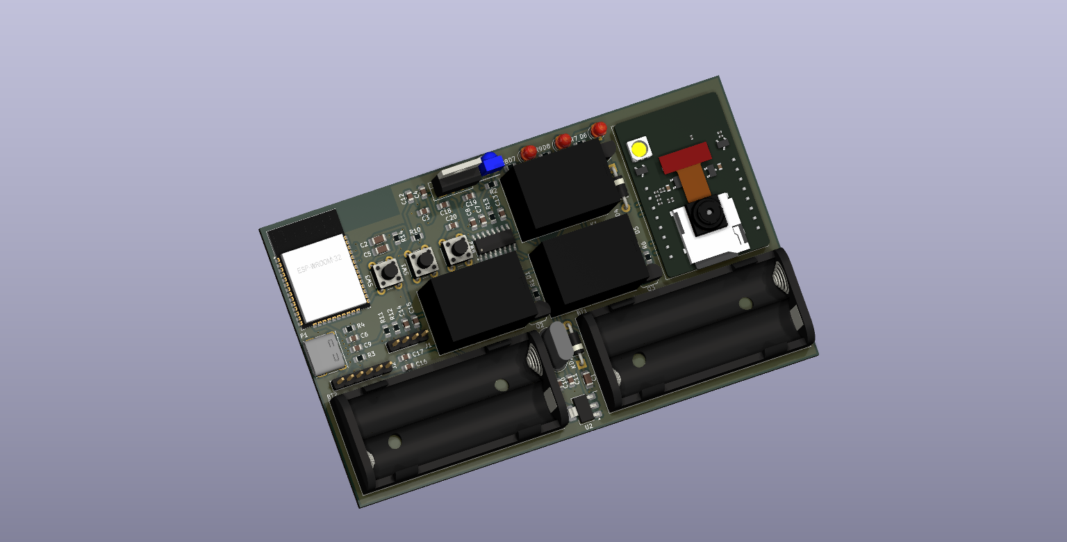
Custom PCB

Custom PCB Design

The custom PCB integrates all components into a single, compact platform, ensuring reliability and scalability. Designed with future enhancements in mind, the PCB minimizes wiring complexity and provides efficient power distribution. Its optimized layout includes thermal management features, ensuring stable performance even under extended operation.

The PCB not only simplifies assembly but also enhances the overall durability and reliability of the system. Its design aligns with modern engineering practices, emphasizing compactness and scalability.

How It Works

Step 1: Room Occupancy Detection

Room Occupancy Detection

The first step involves detecting room occupancy using Passive Infrared (PIR) sensors. These sensors detect motion by identifying changes in infrared radiation levels, which are emitted by human bodies. This data is sent to the ESP32 microcontroller to determine the occupancy state of the room.

  • PIR sensors trigger signals to indicate movement.
  • If no motion is detected for a specified duration, the system powers down connected appliances.
  • The ESP32 dynamically monitors motion data and adjusts system responses.

Step 2: User Authentication

User Authentication

Once motion is detected, the system employs a dual-layer authentication mechanism. This combines facial recognition, handled by the ESP32-CAM, and voice command verification using the serial voice recognition module. Both layers work together to verify the user’s identity.

  • Facial Recognition: Real-time image processing matches facial features against profiles.
  • Voice Commands: Predefined commands, such as "Turn on lights," are validated through the voice module.

Step 3: Appliance and Light Control

Appliance Control

After authentication, the ESP32 microcontroller manages the operation of connected appliances and lights through relay switches. These relays serve as electronic switches that control the flow of electricity to various devices. The system dynamically adjusts its behavior based on user preferences and room conditions.

  • Relays activate appliances based on commands from the ESP32.
  • Lights and devices are turned off automatically when the room becomes unoccupied.

Step 4: Feedback Mechanism

Feedback Mechanism

The system provides immediate feedback to the user regarding its operational state. This feedback includes both visual indicators, such as LED signals, and optional remote notifications through a connected mobile application.

  • LED Indicators: Lights indicate states like motion detected, authentication ongoing, or system idle.
  • Optional App Notifications: Users can receive real-time updates about system activity or errors.

Step 5: System Coordination

System Coordination

At the core of the system is the ESP32 microcontroller, which coordinates all the components. The PIR sensors, ESP32-CAM, relays, and voice module are integrated seamlessly to create a cohesive automation solution. The ESP32 uses communication protocols such as I2C and UART to ensure fast and reliable data exchange between components.

  • I2C: Facilitates data flow from sensors.
  • UART: Handles communication between the ESP32 and the voice module.

Visual Showcase

Overview

The Visual Showcase highlights the core functionalities and design of the Smart Power Management System Using Microcontroller. Below, you’ll find key images and diagrams that represent the system’s innovative features, hardware integration, and real-world applications. Each image is accompanied by a detailed explanation to provide insights into the system’s operation and benefits.

System Overview Diagram

System Architecture Diagram

This diagram illustrates the overall architecture of the system, showing the connections between the ESP32 microcontroller, ESP32-CAM, IR sensors, relays, and other components. It provides a high-level overview of how the system integrates hardware and software for seamless operation.

System Architecture Diagram

Hardware Setup

A detailed image of the assembled hardware highlights the key components:

  • The custom PCB that integrates the ESP32, ESP32-CAM, relays, and voltage regulators.
  • Sensor placement for optimal room coverage.
  • The battery pack and its connection to the voltage regulation circuit.
This setup showcases the compact design and logical organization of the system, emphasizing its scalability and efficiency.

Hardware Setup

Authentication Workflow

This visual demonstrates the dual-layer authentication process. It includes:

  1. Facial recognition via the ESP32-CAM, capturing and processing user images.
  2. Voice command validation using the voice recognition module.
The workflow diagram highlights how these steps work together to ensure secure and personalized access to appliances.

Authentication Workflow

Relay-Controlled Appliance Management

A snapshot of the relay system in action demonstrates how the system controls appliances. The relays activate lights and devices based on room occupancy and authentication signals, ensuring energy-efficient automation.

Relay-Controlled Appliance Management

Energy Consumption Analysis

A graphical comparison of energy consumption before and after implementing the system showcases its efficiency. The data emphasizes the significant energy savings achieved by reducing unnecessary power usage and automating appliance control.

Energy Consumption Analysis
Back to Projects